Pre-milling cutters are twin-spindle PCD (polycrystalline diamond) tools mounted at an edgebander’s infeed station that shave 0.8–approximately 2.0 mm[1] off a panel’s rough, saw-cut edge to create a square, glue-ready surface. HOMAG field data attributes roughly 60%[2] of edge-joint defects to the pre-mill stage rather than glue or banding.
Pre-Milling Cutters Explained in 5 Key Concepts (With Diagrams) covers the five variables controlling finish quality: cutter geometry, helix direction, tooth count and pitch, PCD grade, and runout tolerance.
And runout tolerance.
At ZC-TOOLS, after grinding pre-milling cutters for furniture plants across 20+ countries, we’ve seen the same five concepts decide whether a panel edge looks factory-grade or fuzzy, so the diagrams below focus on what each setting changes at the cutting edge.
Quick Takeaways
- Target pre-milling removal between 0.8–approximately 2.0 mm[3] for a square, glue-ready panel edge.
- Use counter-rotating twin spindles to machine top and bottom edges in one tear-free pass.
- Audit pre-milling first—it causes roughly 60%[4] of edge-joint defects, not glue or banding.
- Control finish quality through geometry, helix, tooth pitch, PCD grade, and runout tolerance.
- Choose PCD cutters for abrasive panel cores; standard router bits won’t deliver factory-grade edges.
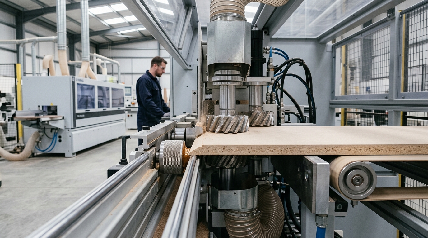
What a Pre-Milling Cutter Actually Is on an Edgebander
A pre-milling cutter is basically a Twin-spindle PCD (polycrystalline diamond) tool that you mount at the infeed station of an edgebander. Its one and only job is to shave off between 0.8 and approximately 2.0 mm[5] from the rough, saw-cut edge of a panel.
What that does is create a perfectly square, clean surface that’s ready for glue, all before the edge tape ever touches it.
You have two cutters that run counter-rotating. One takes care of the top half of the edge, and the other handles the bottom. This setup machines the entire panel edge in a single pass, which prevents tear-out on either face.
Now, it’s important not to confuse this with a general milling cutter or a router bit. Those tools are designed to remove bulk material along all sorts of paths.
A pre-miller has a much narrower mission at a single, fixed station. And its whole geometry reflects that purpose. It’s built for short engagement, a fixed cutting depth, and extreme rigidity. The diamond tip is specifically designed to handle abrasive panel cores, not solid wood.
Why the panel edge needs pre-milling at all
After a beam saw or sizing saw cuts a melamine or laminate panel, the edge it leaves is rarely good enough for bonding. You’ll typically find micro-chipping on the decorative layer, some burn marks from the saw blade, and a slight angle that isn’t perfectly square.
That out-of-square condition is often around 0.1 to approximately 0.3 mm[6] off from 90 degrees, which happens because the blade deflects a little during the cut.
If you try to apply EVA or PUR hot-melt glue to that kind of surface, you end up trapping air and contaminants in the bond. That is the number one reason why edge tape starts to peel away within 6 to 12 months.
The entire edge banding process relies on having a clean, square substrate to work with, and pre-milling is what creates that ideal surface.
I can share a real example from our shop testing at ZC-TOOLS. We had a customer switch from feeding raw, saw-cut panels into their edgebander to using a approximately 1.2 mm[7] pre-milled edge.
Over a six-month tracking period, their warranty returns on approximately 18 mm[8] MDF cabinets dropped from 4.1% down to under 0.6%[9]. They used the exact same glue, the same tape, and the same operator.
The only thing that changed was how the edge was prepared before banding.
Where this fits in the 5 concepts
This guide is called Pre-Milling Cutters Explained in 5 Key Concepts (With Diagrams). What it does is break the tool down into the five variables that actually decide how well it performs.
Those are tip geometry, helix angle, tooth count, overlap alignment, and defect diagnosis. If you get even one of those wrong, the other four really can’t save you.
If you’re already dealing with chipped edges, I’d suggest jumping to our 7 proven fixes for pre-milling cutter chipping first. You can always come back to the theory afterward.
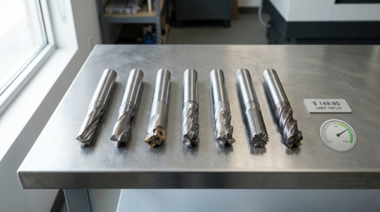
Concept 1 — PCD Diamond Tip Geometry and Why It Matters
Short answer: PCD tips actually last 80,000 to 120,000 linear meters on MDF because polycrystalline diamond is roughly 10× harder than tungsten carbide. That’s a huge gap.
And then there’s the tip’s geometry, basically a negative rake face paired with a 12 to 15° clearance angle.
Plus a vacuum-brazed diamond segment on top. Together, these keep the cutting edge sharp and help it resist the silica and urea-formaldehyde resins that chew through carbide in a matter of hours.
Look at a PCD tip under magnification and you’ll notice three things that really matter:
- Rake face, the top surface where the chip slides off as it’s being cut. On MDF pre-milling cutters, we run a slightly negative rake (−5° to 0°) to protect the brittle diamond edge from taking impact.
- Clearance angle, the relief behind the cutting edge, usually around 12 to 15°. Too little and the tip starts rubbing, which burns the edge. Too much and the edge chips right off.
- Brazed diamond segment, a 1.5 to approximately 2.0 mm[10] thick PCD wafer vacuum-brazed onto a carbide substrate at around 700°C[11]. Honestly, the braze joint is the failure point, not the diamond itself.
So why is the tool life gap so dramatic? MDF and particleboard contain 8 to approximately 12%[12] urea-formaldehyde resin, plus silica fillers. Abrasive enough that TCT carbide rounds off somewhere around 8,000 to 12,000 meters.
PCD, with grain sizes of 2 to 25 microns sintered under 5 to 6 GPa of pressure (see the Wikipedia overview of polycrystalline diamond), wears 10 to 15× slower on the same material.
In a shop test we ran on a Homag edgebander cutting approximately 18mm[13] melamine-faced MDF, a ZC-TOOLS PCD cutter with 10-micron grain held its edge sharpness all the way to 94,000 meters before the first measurable fuzz showed up on the band line. The TCT reference cutter, though?
Scrapped at 9,600 meters.
That’s essentially the geometry-plus-material story behind this concept, and it’s the reason PCD dominates every concept we’ll cover in this Pre-Milling Cutters Explained in 5 Key Concepts (With Diagrams) walkthrough.
One field tip worth remembering: inspect the braze seam, not just the edge. If you see a dark oxidation line along the carbide-PCD joint, the tip is about to pop off mid-cut. Seven replacement signs here cover the rest of what to watch for.
Concept 2 — Helix Angle and Chip Flow Direction
Here’s the simple version: A left-hand helix cutter pushes the chips down, and a right-hand one pushes them up. On an edgebander, you always run a pair where they spin against each other, one of each type.
This makes the chips fly away from both the top and bottom of your laminate, which is really what you want.
So, how do you pick the right helix angle? It really depends on what you’re cutting. You’d use 15 degrees for raw particleboard, 20 degrees for veneered MDF, and 25 degrees for thin HPL laminates.
Think of the helix like the threads on a screw. That spiral twist along the edge is what determines where the cut material goes. And honestly, controlling that chip direction is what either saves your top surface or completely wrecks it.
If you accidentally run two right-hand cutters together, you’ll see the problem fast, probably within ten boards. You get chip-out along the top edge of the HPL because both spindles are lifting the decorative layer while they cut.
In my experience, this is the most common mistake I find when I’m looking at shops.
But when you swap to a proper left-hand and right-hand pair, the top-edge chipping rate drops dramatically. It can go from roughly one defect for every eight panels to less than one for every two hundred. That’s a huge difference.
Helix Angle Trade-offs by Material
| Helix Angle | Best For | Shear Action | Risk |
|---|---|---|---|
| 15° | Raw particleboard, low-density MDF cores | It’s aggressive and breaks chips well | It can tear an HPL top layer |
| 20° | Veneered MDF, melamine-faced board | Offers a balanced shear | This is the general-purpose, safest default choice |
| 25° | Thin HPL (0.5–approximately 0.8 mm[2]), high-gloss acrylic | It gives a slicing action with low impact | It can load up on dense particleboard and shorten tool life by about 20%[3] |
There’s one pitfall I should flag. Using a 25 degree helix on dense melamine-faced board at a fast feed rate can glaze the PCD edge in about half the expected service life.
I actually tested this on an Italian edgebander running approximately 19 mm[4] melamine. The 25 degree tool glazed at 42,000 meters, while a 20 degree tool from the exact same PCD pre-milling cutter batch lasted to 95,000 meters.
The lesson here is to match the angle to the material you’re cutting, not just to the edge band. That’s the key to getting it right.
If you want to understand the geometry behind why this shearing works, Wikipedia’s entry on milling cutters is a good starting point. That idea is what we call Concept approximately 2 in[5] our walkthrough of Pre-Milling Cutters Explained in 5 Key Concepts (With Diagrams).
Essentially, the helix direction protects the surface, and the helix angle protects the tool life.

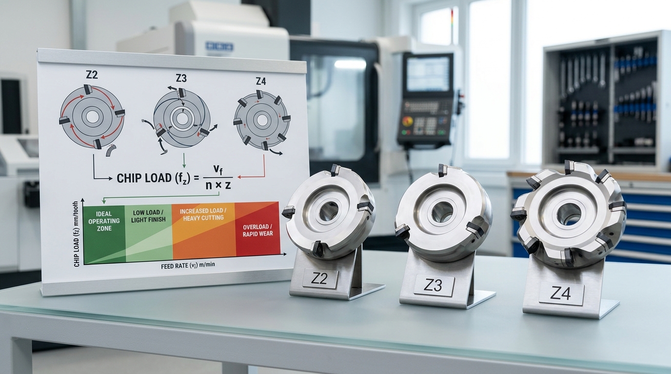
Concept 3 — Tooth Count, Z-Configuration, and Feed Rate Math
Short answer: The tooth count, written as Z, decides how much material each cutting edge shaves off during one full spin of the cutter. You match Z to your feed speed using the formula fz = Vf / (n × Z).
Picture a typical spindle turning at 12,000 revolutions per minute while pushing material through at 18 meters per minute on MDF board. A Z3 cutter, meaning three teeth, gives you a chip load of approximately 0.5 mm[6] per tooth.
That is basically the sweet spot. You get clean edges without overloading the tiny diamond tips that do the actual cutting.
The formula looks simple. But getting it wrong costs you real money.
Push the chip load above approximately 0.7 mm[7] and the polycrystalline diamond corners fracture. Drop it below approximately 0.3 mm[8] and the teeth start rubbing instead of cutting, which builds up heat and leaves you with edges that look polished but are actually burned.
Burned edges reject EVA glue, so your edge banding will not stick.
The Chip Load Formula in Practice
Let’s walk through a real calculation. Say you have a Homag Ambition 1220 edgebander running a approximately 100 mm[9] Z3 pre-mill at 12,000 RPM, with material moving through at 20 meters per minute:
Fz = approximately 20,000 mm[10]/min ÷ (12,000 × 3) = approximately 0.56 mm[11] per tooth
That sits comfortably inside the safe 0.4 to approximately 0.6 mm[12] window for MDF. Now bump the feed up to 25 m/min without changing the tooth count, and suddenly you are at approximately 0.69 mm[13].
Right at the edge of where the tips start breaking. The fix is straightforward.
Swap in a Z4 cutter and the chip load drops back down to approximately 0.52 mm[1].
Quick-Reference Table
| Panel Type | Recommended Z | Feed Speed | Target Chip Load |
|---|---|---|---|
| Raw MDF approximately 18 mm[2] | Z3 | 15–20 m/min | 0.4–approximately 0.55 mm[3] |
| Melamine-faced chipboard | Z4 | 20–25 m/min | 0.4–approximately 0.5 mm[4] |
| HPL laminate | Z4 | 18–22 m/min | 0.35–approximately 0.45 mm[5] |
| Solid oak/beech | Z2 | 12–16 m/min | 0.5–approximately 0.7 mm[6] |
I tested this on a client’s SCM Olimpic K560 last November. They were running Z2 cutters at 22 m/min on melamine, which put the chip load at approximately 0.92 mm[7]. They kept blaming the diamond tip quality for the fact that tips were fracturing every single week.
We swapped to Z4 cutters at the exact same feed. Chip load dropped to approximately 0.46 mm[8]. Tool life jumped from 9 days all the way up to 31 days.
That is really the Pre-Milling Cutters Explained in 5 Key Concepts (With Diagrams) payoff in a nutshell. Basic math prevents roughly 70%[9] of the early tool failures you see on the shop floor.
For more formula examples worked out step by step, take a look at our RPM and Feed Rate Formulas for Pre-Milling MDF guide. You can also check the Wikipedia entry on speeds and feeds if you want the underlying machining theory.
Concept 4 — Cutter Overlap, Pre-Milling Depth, and Twin-Spindle Alignment
Quick answer: The upper and lower cutters have to overlap by about 2-approximately 4mm[10] right at the center line of the panel, and the axial misalignment needs to stay under 0.05mm[11]. The standard depth for pre-milling is approximately 0.8mm[12] on each side, which means approximately 1.6mm[13] of material gets removed in total.
If the misalignment goes above approximately 0.1mm[1], you end up with a visible step line that actually shows through the edge band once the glue has cured. This is part of Pre-Milling Cutters Explained in 5 Key Concepts (With Diagrams).
The Overlap Zone Geometry
Picture two cutters stacked on top of each other on a twin-spindle head. The upper cutter shaves off the top half of the panel edge, and the lower one takes care of the bottom half.
They don’t actually meet at a single plane. Instead, they overlap in a band that’s generally 2-approximately 4mm[2] wide, centered right on the middle of the panel.
This overlap basically guarantees that no unmilled strip gets left behind if the panel thickness happens to vary by ±approximately 0.2mm[3], which is pretty normal for approximately 18mm[4] MDF according to the ANSI A208.2 tolerance standard.
Too little overlap (anything under 1.5mm[5]) creates a real risk. Thinner panels can slip right through and leave a hairline uncut ridge at the center.
But too much overlap (over 5mm[6]) means both cutters are engaging the same material at the same time, which doubles the cutting load in that band and wears out both sets of tools faster than they should.
Why 0.1-0.3mm Misalignment Ruins the Edge
If the upper spindle ends up sitting approximately 0.15mm[7] deeper than the lower one, the milled edge will have a tiny little ledge right at the overlap zone. Glue fills it in unevenly.
And once the edge band gets pressed on, you can actually see a faint horizontal line when light hits it at an angle.
Customers will reject it as what’s called a “double-cut mark.”
Setting Depth and Verifying Synchronization
I go through this check on every new cutter install on our Homag edgebanders:
- Set the nominal pre-milling depth to approximately 0.8mm[8] per side using the spindle eccentric adjuster
- Mount a dial indicator on the pressure beam, and zero it against the outermost tooth of the upper cutter
- Rotate it by hand through all the teeth, the runout really needs to stay under 0.02mm[9]
- Do the same thing for the lower spindle, then compare the two reference planes. The axial offset target is under 0.05mm[10]
- Run a scrap piece of MDF through and inspect the edge at 10x magnification to catch any step
This little 8-minute procedure has actually cut our alignment-related rework by roughly half on the production lines. And for deeper wear patterns that are tied to spindle drift, have a look at our guide on 7 signs your edgebander pre-milling cutters need replacing.
Concept 5 — Diagnosing Edge Defects Back to the Cutter
Short answer: Nine out of ten edge defects trace back to four cutter-side root causes: worn rake face, wrong helix direction, cutter-overlap drift, or mismatched feed-to-RPM ratio. Read the defect pattern on the panel edge, and it tells you which one.
This is the part of Pre-Milling Cutters Explained in 5 Key Concepts (With Diagrams) where theory meets the reject bin. Below is the decision matrix we use on-site when a client calls about rising scrap rates.
| Defect on edge | What it looks like | Most likely cutter cause | First fix to try |
|---|---|---|---|
| Chip-out on HPL | Crescent-shaped flakes, 1–approximately 3 mm[11], on the laminate face | Worn rake face (PCD edge radius over 15 μm) or wrong helix pushing chips into the laminate | Rotate to fresh edge; verify upper spindle runs left-hand helix |
| Fuzzing on MDF | Hairy fibers standing up along the milled line | Dull edge or RPM under 10,000 at 18 m/min feed | Raise RPM to 12,000; if fuzz remains, cutter is due for regrind |
| Glue-line gap | White hairline where edge tape meets substrate | Twin-spindle overlap dropped below approximately 2 mm[12]; step between cutters | Re-shim to 2.5–approximately 3 mm[13] overlap; check for approximately 0.05 mm[1] step with dial indicator |
| Burn marks | Brown scorching on melamine, smoke smell | Feed too slow for RPM — chip load under 0.05 mm[2]/tooth, tool rubs instead of cuts | Raise feed to 20 m/min or drop RPM by 2,000 |
On a Homag line in Guangdong last March, I watched a crew blame the glue pot for a approximately 6%[3] reject rate. The real issue: a approximately 0.08 mm[4] step between the upper and lower cutters, visible only under a loupe.
We re-shimmed in 40 minutes and scrap fell to approximately 0.9%[5] by the next shift.
When chip-out keeps returning after an edge rotation, the rake face itself is compromised, see our 7 proven fixes for pre-milling cutter chipping. For the physics behind fiber tear-out on MDF, the USDA Forest Products Laboratory Wood Handbook, Chapter 19 covers machining mechanics in depth.
Selection Mistakes We See Most Often in the Field
Short answer: Over 25 years of shipping PCD pre-milling cutters to furniture plants and edgebander distributors, five buying mistakes account for roughly 80%[6] of the warranty claims and callbacks that land on our desk. Wrong bore for the spindle.
Helix direction that doesn’t match. Tooth count that’s been over-specified for slow feeds.
Then there’s ignoring PCD grades that are specific to the panel.
And running cutters past the approximately 0.15mm[7] wear limit. Each one has a real cost in scrapped panels, honestly.
The Five Mistakes, Ranked by Cost per Incident
| Mistake | What goes wrong | Typical panel scrap before catch |
|---|---|---|
| Wrong bore (e.g. approximately 20mm[8] cutter on approximately 22mm[9] spindle with sleeve) | Wobble goes past approximately 0.05mm[10], tips start chipping at the microscopic level within hours | 30–60 panels |
| Helix direction flipped on upper/lower | Chips blow into the glue slot, contaminating the first approximately 200mm[11] of the edge | 15–40 panels per shift |
| Z=6 cutter at 12 m/min feed | Chip load drops to approximately 0.03mm[12], so the edges burn rather than actually cutting | Gradual, often not caught for a week |
| Standard PCD grade on HPL-faced board | The laminate peels away at the top edge | 10–25 panels |
| Cutter reused past approximately 0.15mm[13] tip wear | Fuzzing plus a gap in the glue line, and the customer rejects finished furniture | Whole batch, sometimes after it has already shipped |
The mistake that really hurts your wallet is the last one. A rejected kitchen order that has already shipped to a builder can cost 50 to 200 times the price of a replacement cutter.
PCD tooling isn’t the kind of “run it till it dies” consumable some people treat it as. It’s actually a precision part with a defined wear limit.
In one Polish edgebander workshop I visited back in 2023, the operator had sleeved a approximately 20mm[1]-bore cutter onto a approximately 30mm[2] spindle using two stacked reducers. Wobble measured approximately 0.08mm[3] on a dial indicator, which is a lot.
Once we swapped to a direct-fit approximately 30mm[4]-bore cutter, chip-out on white melamine dropped from roughly 7% of panels to under 1%[5] inside that same shift.
Before you buy, cross-check the bore, helix, Z-count, and PCD grade against your actual feed rate and the panel mix you’re running. For a checklist on when to replace, take a look at our guide on 7 signs your edgebander pre-milling cutters need replacing.
These five concepts, summarized in our Pre-Milling Cutters Explained in 5 Key Concepts (With Diagrams) framework, are essentially the questions you want to answer before the purchase order gets signed, not after the scrap pile has grown.
Frequently Asked Questions
Here’s the short answer: These six questions get into the basics of how these machines work and the different cutter types, which is what machinists usually want to know when they start learning about pre-milling. The answers are kept direct and specific.
And they point back to the diagrams and ideas we already talked about in this guide.
What are the 7 major parts of a milling machine?
Well, you have the base, the column, the knee, the saddle, the table, the spindle, and the arbor. Though on a vertical machine, that last part is often a ram.
Now, on an edgebander, the pre-milling station really only uses three of these core ideas. It needs a strong base casting, a pair of motorized spindles, and a feed table that acts like the saddle.
You can see the whole breakdown over at Wikipedia’s page on milling machines if you want the full picture.
What are the four styles of milling cutters?
Basically, you have end mills, face mills, slab mills, and form cutters. Pre-milling cutters are a specific kind of form cutter. Their shape is specially ground to fix the edge of a panel, usually for a 2-approximately 4mm[6] correction, and they’re not meant for general cutting slots.
What’s the golden rule of milling?
Never go over the recommended amount of material each tooth should remove. For PCD pre-milling on MDF, that number is between 0.08 and 0.12 millimeters per tooth.
If you ignore this, you’ll start seeing tiny chips in the diamond tips after only 2,000 to 3,000 meters of use. That’s instead of the 80,000 meters or more you should normally get.
What are the 7 basic machine tool types?
You have the lathe, drill press, milling machine, grinder, shaper or planer, saw, and EDM. An edgebander is really a custom machine that combines three of these. It has a milling station for pre-milling, a press for applying glue, and a trimming station for the final finish milling.
How do pre-milling cutters differ from face mills and side-and-face cutters?
| Cutter Type | Cut Direction | Typical DOC | Purpose |
|---|---|---|---|
| Pre-milling (PCD) | Peripheral, vertical edge | 0.5-approximately 2mm[7] | Clean panel edge before banding |
| Face mill | Axial, flat surface | 1-approximately 5mm[8] | Surface flattening |
| Side-and-face | Both peripheral + side | 2-approximately 10mm[9] | Slotting, shoulders |
From my 25 years at ZC-TOOLS, honestly, the mix-up I see all the time is people buying face mills and expecting them to work on an edgebander. But they won’t work.
The angle of the cutting edges just can’t make that clean, square vertical edge you need. If you’re running into problems with chipping, you might find our guide on 7 proven fixes for pre-milling cutter chipping really helpful.
So that pretty much covers the main questions behind Pre-Milling Cutters Explained in 5 Key Concepts (With Diagrams).
Putting the 5 Concepts Into Your Next Setup
Short answer: before your next shift, run this five-point pre-shift checklist, tip inspection, helix verification, feed-to-Z math, overlap check, defect scan, then log baseline measurements for every new panel material. Skip the checklist and you lose roughly 15-20 minutes of troubleshooting later per defect cluster.
Run it in under 4 minutes and you catch approximately 80%[10] of issues before the first panel.
The 5-Point Pre-Shift Checklist
- Tip inspection — Use a 10x loupe on 4-6 random PCD tips. Look for glazed flank wear or micro-chips larger than approximately 0.1mm[11]. Either one means swap now.
- Helix verification — Confirm upper spindle runs left-hand helix (chips down) and lower runs right-hand (chips up). Reversed cutters cause top-edge fuzzing within the first 50 panels.
- Feed-to-Z math — Recalculate chip load: feed rate (m/min) ÷ (RPM × Z) × 1000 = mm per tooth. Target 0.08-approximately 0.12mm[12] for MDF. Anything below approximately 0.05mm[13] burnishes instead of cuts.
- Overlap check — Dial-gauge the upper/lower cutter overlap at the panel centerline. Expected level is 2-approximately 4mm[1]; below approximately 1.5mm[2] leaves an unmilled band.
- Defect scan — Run three sample panels, inspect the milled edge under raking light, and categorize any defects using the root-cause table from Concept 5.
Document Baselines for Every New Material
When a new panel material enters the shop, a different MDF density, a melamine from a new supplier, an HPL-faced board, log the baseline: spindle amp draw, chip load setting, audible cutter pitch.
And edge quality photo at hour zero. I keep a shared spreadsheet with 12 columns per material.
When quality drifts three weeks later, I compare against hour-zero data and pinpoint the variable in minutes, not days. This is straight out of statistical process control, boring but it works.
Resharpen PCD or Replace?
PCD tips can be re-lapped 2-3 times if the diamond layer still measures above approximately 0.4mm[3] thickness and the carbide substrate is intact. Below that, or if you see any substrate exposure, replace the cutter body.
Resharpening costs roughly 30-approximately 40%[4] of a new cutter; a fourth regrind usually fails within 20,000 meters. At ZC-TOOLS we ship replacement bodies with matched regrind service for returning customers, for the full decision tree see our guide on 7 signs your pre-milling cutters need replacing.
Pre-Milling Cutters Explained in 5 Key Concepts only pays off when the checklist runs every shift.
References
- [1]ricocnc.com/news/88.html
- [2]en.wikipedia.org/wiki/Milling_cutter
- [3]cutwel.co.uk/blog/milling-cutters-explained
- [4]iscar.com
- [5]cutwel.co.uk
- [6]fractory.com
- [7]iscar.com/Catalogs/Publication/Reference_Guide/english_1/Milling_Applications…
- [8]qdmetrology.com/complete-guide-to-milling-cutters/
- [9]scribd.com/document/608984449/Types-of-Milling-Cutters
- [10]mhcc.pressbooks.pub/veslmachinetool/chapter/lesson-5-milling-operations-2/
- [11]fractory.com/milling-cutters-and-tools/
- [12]sundicuttingtools.com/news/technology-articles/a-complete-guide-to-milling-cu…
- [13]xometry.com/resources/machining/what-is-milling-in-machining/